Node-RED eMOD API Modules
Node-RED allows you to focus on what really matters, our added value to the solutions.
We have gone one step further on the integration of eManager and Node-RED creating customized nodes for each of our expansion modules.


This Getting Started guide covers setting up eMOD nodes, with a description of what each can do, what functions are available, along with usage examples for each of the eMOD nodes.
No Installation required
The eManager is shipped with preinstalled eMOD nodes corresponding to the installed hardware modules.
Note
For testing purposes we have developed simulation nodes. All the information related to the usage of this nodes can be found here.
8SR
Connects to a 8SR eMOD module (datasheet) to manage the 8 relays individually or jointly.

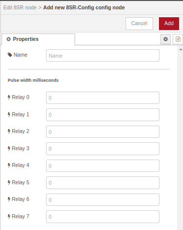
Some parameters must be configured in the node before start using it, as shown in the image above. Those parameters are:
- Pulse width miliseconds: A pulse width for the 8 relays must be defined in the configuration node. By default, it is set to 0 value.
For more information about the module and different configuration options, please check here.
Functions
- get_one: obtains the status of a single relay.
Example
To obtain the status of the relay 0 you can use:
{"status": {"index":0, "value":false}}.
- get_all: obtains the status of all relays.
Example
To obtain the status of all relays you can use:
In this case, the first and fourth relays are on:{"all_status": [true, false, false, true, false, false, false, false] }.
- set_one: activates or deactivates a single relay. On completion of action, input message with result is sent to output port.
Example 1
Activates relay 0:
The output tells us that relay 0 is on :{"status": {"index":0, "value":true}}.
Example 2
Deactivates relay 0:
The output tells us that relay 0 is off:{"status": {"index":0, "value":false}}.
-
set: activates or deactivates some relays. On completion of action, input message with result is sent to output port. As a parameter, it has an 8-element array of one among the following:
- true: activates relay.
- false: deactivates relay.
- null: does not change the status of the relay.
Example
Activate the first and fourth relays and deactivate the eighth:
The output tells us all relay status:{"all_status":[true,true,true,true,false,true,false,false]}.
- set_all: activates or deactivates all relays. On completion of action, input message with result is sent to output port.
Example 1
To activate all relays:
The output tells us all relay status: {"all_status":[true,true,true,true,true,true,true,true]}.
Example 2
To deactivate all relays:
The output tells us all relay status:{"all_status":[false,false,false,false,false,false,false,false]}.
10DI
Connects to a 10DI eMOD module (datasheet) to manage the 10 digital inputs individually or jointly.

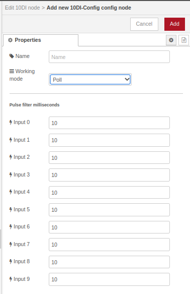
Some parameters must be configured in the node before start using it, as shown in the image above. Those parameters are:
- Working mode: It must be specified if we want to make the node work in Poll mode or in Event mode. By default, it is set to Poll mode.
- Pulse filter milliseconds: It must be specified the filter that we want to use for each digital input. By default it is set to 10ms.
For more information about the module and different configuration options, please check here.
Functions
- get_one (only in Poll mode): obtains the status or pulse count of a single digital input.
Example 1
To obtain the status of a single digital input:
In this case, fourth digital input is in high state:{"status": {"index": 3, "value": true}}.
Example 2
To obtain the pulse count of a digital input:
In this case, pulse count of fourth digital input is 15:{"counter": {"index": 3, "value": 15}}.
- get_all (only in Poll mode): obtains the status or pulse count of all digital inputs.
Example 1
To obtain the status of all digital input:
In this case, only fourth digital input is high state:{"all_status": [false, false, false, true, false, false, false, false, false, false] }.
Example 2
To obtain the pulse count of all digital input:
Function returns following pulse counts:{"all_counters": [0, 5, 10, 2, 23, 5, 71, 3, 0, 0] }.
- reset_pulse_count: resets one or all inputs.
7AI+2PR
Connects to a 7AI+2PR eMOD module (datasheet) to manage the 7 analog inputs and 2 relays individually or jointly.

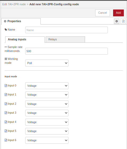
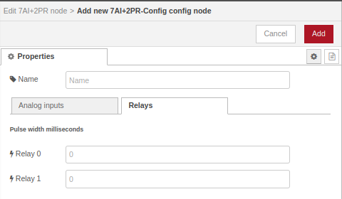
Some parameters must be configured in the node before start using it, as shown in the image above. Those parameters are:
- Working mode: It must be specified if we want to make the node work in Poll mode or in Event mode. By default, it is set to Poll mode.
- Input mode: It must be specified if we want to get voltage or current values from the node. By default, it is set to voltage.
- Pulse width milliseconds: A pulse width for the 2 relays must be defined in the configuration node. By default, it is set to 0 value.
This module has 2 output: one for the relays and the other for the analog inputs.
For more information about the module and different configuration options, please check here.
Analog inputs functions
- ai_get_one (only in Poll mode): obtains the value of a single analog input.
Example
To obtain the value of a single analog input:
In this case, fourth analog input is configured as voltage and its value is 3.1 V:{"voltage": {"index": 3, "value": 3.1}}.
- ai_get_all (only in Poll mode): obtains the value of all analog inputs.
Example
To obtain the value of all analog inputs:
In this case, the first three inputs are configured as voltage and the rest as current. Each one has a different value:{"values": [
{"voltage": {"index": 0, "value": 5.2}},
{"voltage": {"index": 1, "value": 3.2}} ,
{"voltage": {"index": 2, "value": 4.8}},
{"current": {"index": 3, "value": 0.3}},
{"current": {"index": 4, "value": 0.2}},
{"current": {"index": 5, "value": 0.4}},
{"current": {"index": 6, "value": 0.3}}
]}
Relays functions
- relay_get_one: obtains the status of a single relay.
Example
To obtain the status of the relay 0:
In this case, the response tells us that relay 0 is off:{"status": {"index":0, "value":false}}.
- relay_get_all: obtains the status of all relays.
Example
To obtain the status of all relays:
In this case, only the first relay is on:{"all_status": [true, false]}.
- relay_set_one: activates or deactivates a single relay. On completion of action, input message with result is sent to output port.
Example 1
Activates relay 0:
The output tells us that relay 0 is on:{"status": {"index":0, "value":true}}.
Example 2
Deactivates relay 0:
Output tells us that relay 0 is off:{"status": {"index":0, "value":false}}.
-
relay_set: activates or deactivates some relays. On completion of action, input message with result is sent to output port.
As a parameter, it has an 8-element array of one among the following:- true: activates relay.
- false: deactivates relay.
- null: does not change the status of the relay.
Example
Activate the first and deactivate the second:
Output tells us all relay status:{"all_status":[true,false]}.
- relay_set_all: activates or deactivates all relays. On completion of action, input message with result is sent to output port.
Example 1
To activate all relays:
Output tells us all relay status:{"all_status":[true,true]}.
Example 2
To deactivate all relays:
Output tells us all relay status:{"all_status":[false,false]}.
12AI
Connects to a 12AI eMOD module (datasheet) to manage the 12 analog inputs individually or jointly.
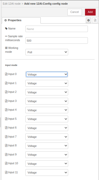
Some parameters must be configured in the node before start using it, as shown in the image above. Those parameters are:
- Working mode: It must be specified if we want to make the node work in Poll mode or in Event mode. By default, it is set to Poll mode.
- Input mode: It must be specified if we want to get voltage or current values from the node. By default, it is set to voltage.
For more information about the module and different configuration options, please check here.
Functions
- ai_get_one (only in Poll mode: obtains the value of a single analog input.
Example
To obtain the value of a single analog input:
In this case, fourth analog input is configured as voltage and its value is 3.1 V:{"voltage": {"index": 3, "value": 3.1}}.
- ai_get_all (only in Poll mode): obtains the value of all analog inputs.
Example
To obtain the value of all analog inputs:
In this case, the first three inputs are configured as voltage and the rest as current. Each one has a different value:{"values": [
{"voltage": {"index": 0, "value": 5.2}},
{"voltage": {"index": 1, "value": 3.2}},
{"voltage": {"index": 2, "value": 4.8}},
{"current": {"index": 3, "value": 0.3}},
{"current": {"index": 4, "value": 0.2}},
{"current": {"index": 5, "value": 0.4}},
{"current": {"index": 6, "value": 0.3}}
]}
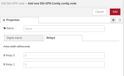
5DI+2PR
Connects to a 5DI+2PR eMOD module (datasheet) to manage the 5 digital inputs and 2 relays individually or jointly.

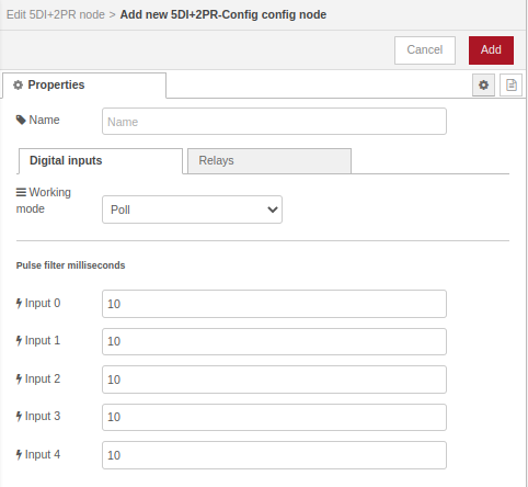
Some parameters must be configured in the node before start using it, as shown in the image above. Those parameters are:
- Working mode: It must be specified if we want to make the node work in Poll mode or in Event mode. By default, it is set to Poll mode.
- Pulse filter milliseconds: It must be specified the filter that we want to use for each digital input. By default it is set to 10ms.
- Pulse width milliseconds: A pulse width for the 2 relays must be defined in the configuration node. By default, it is set to 0 value.
For more information about the module and different configuration options, please check here.
Digital input functions
- di_get_one (only in Poll mode): obtains the status or pulse count of a single digital input.
Example 1
To obtain the status of a single digital input:
In this case, fourth digital input is in high state:{"status": {"index": 3, "value": true}}.
Example 2
To obtain the pulse count of a digital input:
In this case, pulse count of fourth digital input is 15:{"counter": {"index": 3, "value": 15}}.
- di_get_all (only in Poll mode): obtains the status or pulse count of all digital inputs.
Example 1
To obtain the status of all digital input:
In this case, only fourth digital input is high state:{"all_status": [false, false, false, true, false, false, false, false, false, false]}.
Example 2
To obtain the pulse count of all digital input:
Function returns following pulse counts:{"all_counters": [0, 5, 10, 2, 23, 5, 71, 3, 0, 0]}.
- reset_pulse_count: resets one or all inputs.
Relay functions
- relay_get_one: obtains the status of a single relay.
Example
To obtain the status of the relay 0:
In this case, the response tells us that relay 0 is off:{"status": {"index":0, "value":false}}.
- relay_get_all: obtains the status of all relays.
Example
To obtain the status of all relays:
In this case, only the first relay is on:{"all_status": [true, false]}.
- relay_set_one: activates or deactivates a single relay. On completion of action, input message with result is sent to output port.
Example 1
Activates relay 0:
Output tells us that relay 0 is on:{"status": {"index":0, "value":true}}.
Example 2
Deactivates relay 0:
Output tells us that relay 0 is off:{"status": {"index":0, "value":false}}.
-
relay_set: activates or deactivates some relays. On completion of action, input message with result is sent to output port.
As a parameter, an 2-element array of one among the following:- true: activates relay.
- false: deactivates relay.
- null: does not change the status of the relay.
Example
Activate the first and deactivate the second:
Output tells us all relay status:{"all_status":[true,false]}.
- relay_set_all: activates or deactivates all relays. On completion of action, input message with result is sent to output port.
Example 1
To activate all relays:
Output tells us all relay status:{"all_status":[true,true]}.
Example 2
To deactivate all relays:
Output tells us all relay status:{"all_status":[false,false]}.
EM3/EM3_250
Connects to 3 Phase Energy Meter module (datasheet) and gets the parameters.

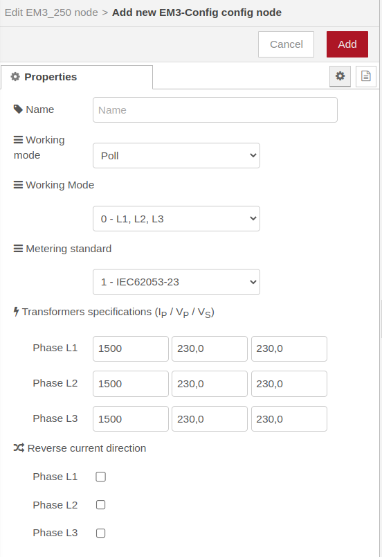
Some parameters must be configured in the node before start using it. Those parameters are:
- Working mode: By default, the first working mode is defined to Poll. In the second working mode, it must be specified how the different variables of each phase (L1, L2 and L3) are connected to the module (one-phase connection or three-phase connection). Four different working modes has been defines taking into account the different possible scenarios.
- Metering standard: The settlement used in the measurements must be specified. There are 3 different metering standards (Circutor, IEC62053-23 or IEEE 1459-2000).
- Transformers specifications(new in image release 22.10): Each column must be filled with the Current Transformer specifications. From left to right the columns contain:
- First column: principal current (IP) in mA.
- Second column: principal voltage (VP) in V.
- Third column: secondary voltage (VS) in V.
- Reverse current direction(new in image release 22.10): It toggles the current direction of any phase, to avoid modifying connections already installed.
For more information about the module and different configuration options, please check here.
Functions
- get: Gets "power" or "energy" related parameters of any phase ("L1", "L2", "L3") or their combined results ("L123"). It can also get all parameters at once.
Examples
-
To obtain the parameters relative to accumulated energy on phases one, two and three and their combined results:
-
To obtain the parameters relative to the combined results of accumulated energy on phases one, two and three:
-
To obtain the parameters relative to instant power on phase one:
-
To obtain all the parameters:
- reset: Set all energy meter counters back to 0:
Return value
The "get" command triggers a msg.payload at the output of the node EM3/EM3_250, which is a list of "key":value pairs. Every parameter is autodescriptive, the prefix indicating the mesured variable, the suffix indicating the input phase, L1, L2, L3 or L123 (for combined calculated values). An example of output is as follows:
{"power_L3":
    {"voltage": "230.2",
    "current": "491",
    "frequency": "50",
    "cosine": "0.997",
    "angle" : "85.61", ...}
}
Units
| Parameter | Unit |
|---|---|
| voltage | V |
| current | A |
| frequency | Hz |
| angle | Degree |
| active_power | kW |
| aparent_power | kVA |
| reactive_power | kVAr |
| inductive_power | kVArl |
| capacitive_power | kWArl |
| active_energy | kWh |
| aparent_energy | kVAh |
| reactive_energy | kVArh |
| inductive_energy | kVArlh |
| capacitive_energy | kVArlh |
2DI+1PR+2T
Connects to a 2DI+1PR+2T eMOD module (datasheet) to manage the 2 digital inputs, 1 relay and 2 Temperature inputs individually or jointly.
This module only supports two different types of temperature sensors, which are PT100 and PT1000.

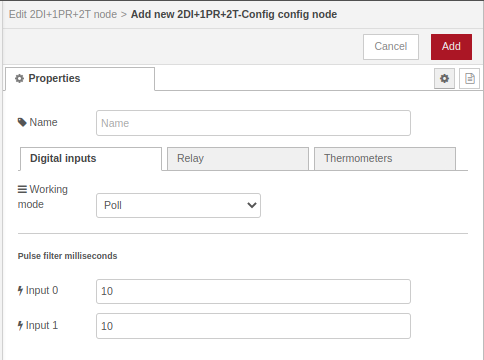
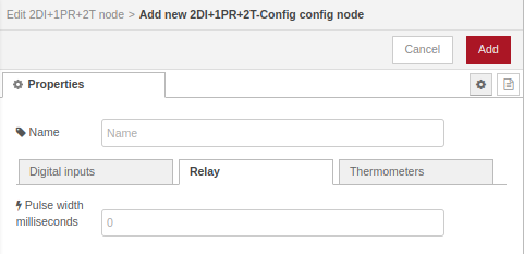
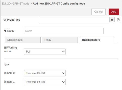
Some parameters must be configured in the node before start using it, as shown in the image above. Those parameters are:
- Working mode: It must be specified if we want to make the node work in Poll mode or in Event mode. By default, it is set to Poll mode.
- Pulse filter milliseconds: It must be specified the filter that we want to use for each digital input. By default it is set to 10ms.
- Pulse width milliseconds: A pulse width for the 2 relays must be defined in the configuration node. By default, it is set to 0 value.
- Type: It corresponds to the type of the temperature sensors. By default, it is set to Two wire Pt100.
For more information about the module and different configuration options, please check here.
Digital input functions
- di_get_one (only in Poll mode): obtains the status or pulse count of a single digital input.
Example 1
To obtain the status of a single digital input:
In this case, the second digital input is in high state: {"status": {"index": 1, "value": true}}.
Example 2
To obtain the pulse count of a digital input inject:
In this case, first digital input pulse count is 15:{"counter": {"index": 0, "value": 15}}.
- di_get_all (only in Poll mode): obtains the status or pulse count of all digital inputs.
Example 1
To obtain the status of all digital input:
In this case, only fourth digital input is high state:{"all_status": [false, true]}.
Example 2
To obtain the pulse count of all digital input:
Function returns following pulse counts:{"all_counters": [1, 59]}.
- reset_pulse_count: resets one or all inputs.
Relay functions
- relay_get: obtains the status of the relay.
Example
To obtain the status of the relay inject:
In this case, the relay is on:{"status": true}.
- relay_set: activates or deactivates the relay. On completion of action, input message with result is sent to output port.
Example
- Activate the relay:
Output tells us all relay status:
{"status": true}. - Deactivate the relay:
Output tells us all relay status:
{"status": false}.
Thermometer functions
- temp_get_one (only in Poll mode): obtains the themperature of a single thermometer. The result is sent to the Thermometers output port.
Example
To obtain the temperature of a single thermometer inject:
Return message payload is:{"status":{"index":1,"value":22.73}}.
- temp_get_all (only in Poll mode): obtains the temperature of all thermometers. The result is sent to the Thermometers output port.
Example
To obtain the temperature of each thermometer inject:
Return message payload is:{"all_status":[-5.99,22.74]}.
Thermometers take special values when an anomaly is detected. Those are:
- -200.99 is sent when unplugged thermometer.
- ±299.99 is sent when wrongly configured thermometer (only in event mode).
Supercap
Allows Supercapacitor module (datasheet) notifies when there is a power source change.
It has one output:
- Power source change: notifies when power source switches from external power (AC) to internal (if supercap module is present), or vice versa. When power source switches from external power (AC) to internal (supercap), message payload is: When power source switches from internal (supercap) to external power (AC), message payload is:
For more information about the module, please check here.
Modules restrictions
- One module entries only can be configured in polling mode or event mode, but never with both work modes at the same time.
- If a module has inputs and outputs, the inputs can be configured in event mode and there will be no problem operating on the outputs in polling mode.
- In polling mode there can be as many nodes as needed, but they have to use the same configuration node.
- If there are more than one module of the same type, in event mode there can only be one node, which is the one that receives events.
Recommendation
Create only one configuration node (e.g. 10DI-Config). If several are created only one will be active.
Multiple modules of the same type
- In both polling and event mode, two or more nodes associated to different hardware modules (with the same type) can share the same configuration node. This can simplify configuration where possible.
- The same hardware module cannot have two different configuration nodes assigned.