Node-RED Flow Examples
How to read a digital input?
If we want to read a digital input we can start by placing the eMOD node with digital inputs that you are going to use in the middle of the Node-RED dashboard. Currently, the available eMOD nodes with digital inputs are: 10DI and 5DI+2PR. In this example we are going to use the 10DI node.
Then, it is necessary to add an inject node to be able to manually trigger a flow.
Finally, a debug node is added to see the payloads obtained from the messages. The flow obtained is the one shown in the image below.
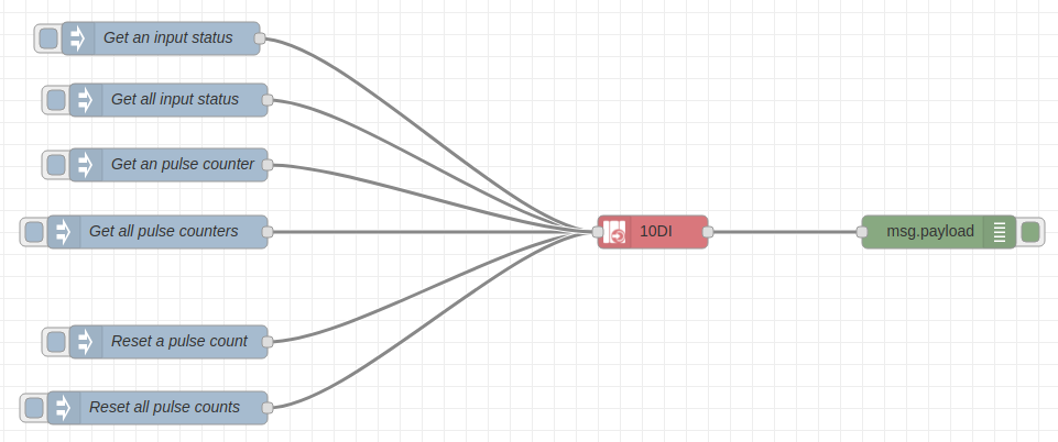
For more information regarding this module's functions, please check here.
Click here if you want to be able to get the flow code.
How to activate and deactivate a relay?
If we want to work with a relay we can start by placing the eMOD node with relays that you are going to use in the middle of the Node-RED dashboard. Currently, the available eMOD nodes with relays are: 8SR, 5DI+2PR and 7AI+2PR. In this example we are going to use the 8SR node.
First, an inject node must be added.
Finally, a debug node is added to see the payloads obtained from the messages. The flow obtained is the one shown in the image below.
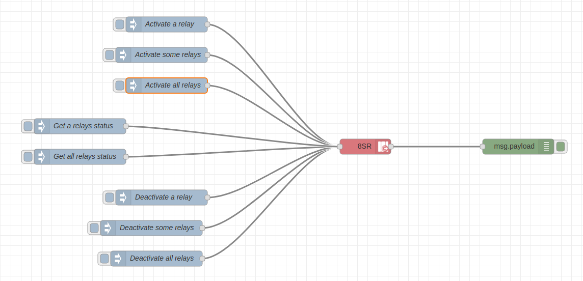
For more information regarding this module's functions, please check here.
Click here if you want to be able to get the flow code.
How to configurate Modbus to read one or multiple variables?
To work with the Modbus protocol in this example, we are going to use the SEM Three device as an input device.
First of all, the setup must be prepared properly and the connections between the eManager and the SEM Three device must be verified. To do so:
- Check the power supply of the SEM Three device and verify that the ON led is in green.
- Check the connections between the eManager and the SEM Three. The A+, B- and GND outputs of the SEM Three must be connected to the modbus input of our eManager.
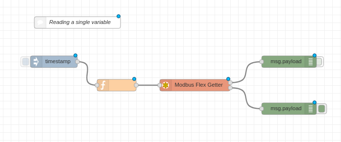
Example 1: Reading a single variable
To read a single variable we are going to use:
- An
inject nodewith the timestamp -
A
function nodewith the following code:In this case we are communicating with the SEM Three, which has 72 as a default unitid, using function number 4 and reading the register with address 2, which has 2 bytes length. If you want to read other parameters or configuration modes of the SEM Three, please check the Modbus RTU Memory Map on the device datasheet.
-
The
modbus flex gettermodule. - The
debug nodewith the message payload.
The flow obtained for this example is shown in the image below.
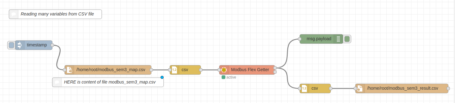
Example 2: Reading multiple variables using a .csv file
To read multiple variables through Modbus protocol we are going to use .csv files to store the coonfigurations (unitid, fc, address and quantity) needed for the different variables. We are going to use the following nodes:
- An
inject nodewith the timestamp. -
A
file node. In this case we need to store a.csvfile named modbus_sem3_map.csv in/home/root/with the following content: -
Two
csv nodeswhere columns and separators are indicated. - The
modbus flex gettermodule. - The
debug nodewith the message payload. - Another
file node. We will store the results in a.csvfile named modbus_sem3_result.csv in the path/home/root/.
The flow obtained for this example is shown in the image below.
Click here if you want to be able to get the flow code for both cases.
How to write a variable using Modbus protocol?
To work with this Modbus example, we are going to use the ACTIO 24 device. We are going to write variables using Modbus to that device.
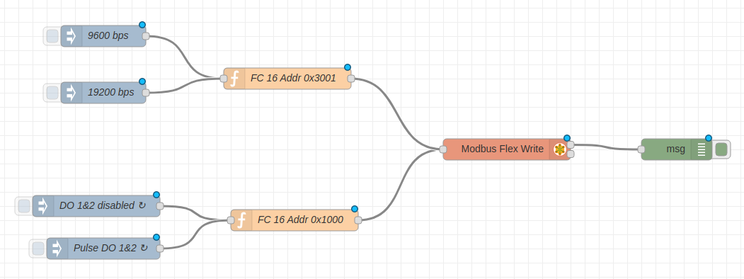
We will see in the flow created that this example is able to modify the communication baudrate (9600 or 19200) and to control the digital outputs by opening and closing them. To do so, we are going to use:
- 4
inject nodes: two nodes with different baudrates (9600 and 19200) and the other two for activating and deactivating the digital inputs 1 & 2. - 1
function nodeto write the baudrate into an specific register, using the following code: -
1
function nodeto activate and deactivate the digital inputs, using the following code: -
The
modbus flex-write node. - The
debug nodeto see the message payload.
The flow obtained for this example is shown in the image below.
Click here if you want to be able to get the flow code.
How to read an analog input?
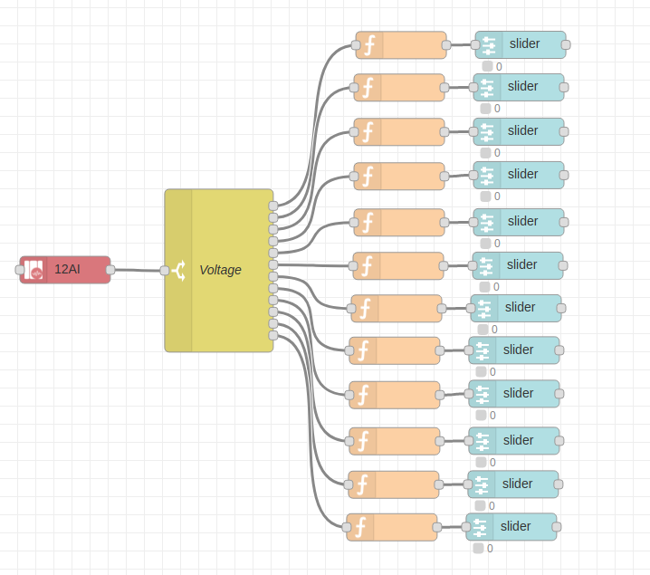
If we want to read an analog input we can start by placing the eMOD node with analog inputs that you are going to use in the middle of the Node-RED dashboard. Currently, the available eMOD nodes with analog inputs are: 12AI and 7AI+2PR. In this example we are going to use the 12AI node.
To do so, we need to use the following modules:
- The 12 AI module.
- A
switch nodeto be able to see all the inputs at once. - A
function nodewith the following code: - A
slider node.
Note
To be able to use the slider node it is necessary to have installed the dashboard package.
Note
In order to read the input's current, change the switch node configuration Property field for payload.current.index
The flow obtained for this example is shown in the image below.
For more information regarding this module's functions, please check here.
Click here in order to get the flow code.
How to write files with atomicity?
Important information for eManagers (non-Pro).
If we want to write a file with the certainty that the information will be written correctly, we have to do it with atomicity.
For more information on how to write to files in an eManager, read the following article.
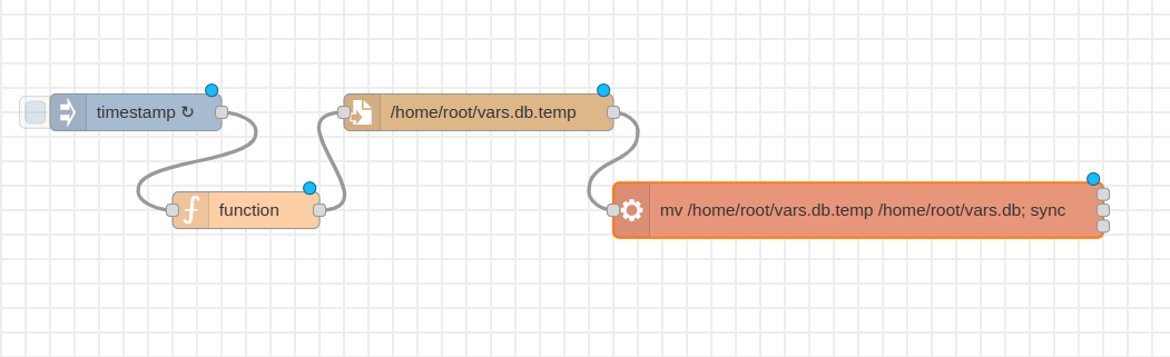
In this example we are going to write some data in a temporary file, and once it is written, we are going to write a definitive file using the atomic command mv and make a sync to ensure the file has been written properly.
To do so, we need to use the following modules:
- An
inject node. - A
function nodethat produces the data to be stored in file. - A
write file node - An
exec node, which allows you to take any existing system command and run it from Node-RED and incorporate the results in your flow. In this example, this node uses the atomic commandmvto copy the content of the temporary file to the final file and performs asyncto avoid any data loss.
The flow obtained for this example is shown in the image below.
Click here in order to get the flow code.