EM3/EM3_250 Module
This module has its own microcontroller
Two models avaialbe:
-
The EM3 module with current transformer output of 1A.
-
The EM3_250 module with current transformer output of 250mA.
The EM3/EM3_250 module (datasheet 1A model) is a 4 quadrant energy meter, which bet on professional accuracy Class 1 Active and Class 2 Reactive and skip measurement deviations.
Some parameters must be configured before starting different measurements. In this section all of them will be defined.
Information about how to program this node using Node-RED can be found here. Otherwise, if you want to develop your own applications using the multilanguage API, please check here for more information.
Working mode configuration
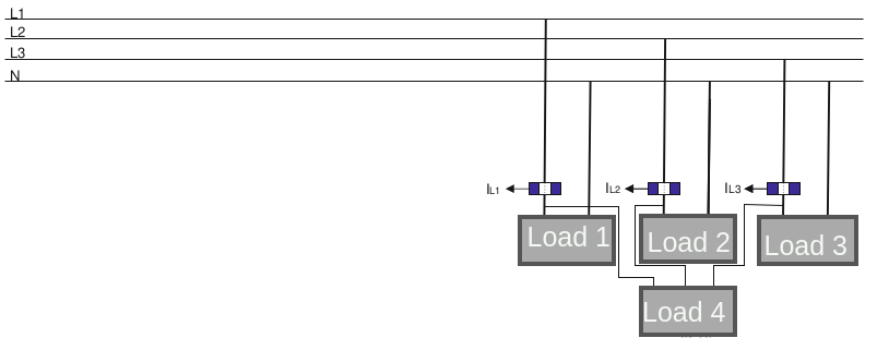
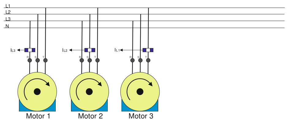
1. Mode 0
It is the default mode configured in the module. In this configuration each phase is individual, and the computation of the three of them are the three-phase variables.
As shown in the image below, it is possible to have three single-phase individual loads and see the measured parameters in one or three-phase form.
2. Mode 1
If this mode is chosen, L1 is able to measure a three-phase load. So, the module is able to measure a three-phase balanced load as it was single-phase.
The current, power and energy parameters measured in L1 will be multiplied by 3 in each parameter, since it is a balanced three-phase load.
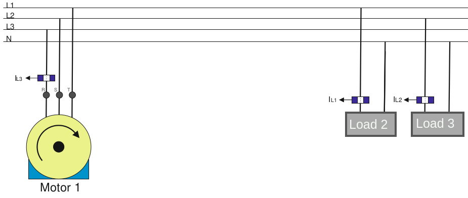
3. Mode 2
If this mode is chosen, L1 and L2 are able to measure a three-phase load. So, the module is able to measure a three-phase balanced load as it was single-phase.
The current, power and energy parameters measured in L1 and L2 will be multiplied by 3 in each parameter, since it is a balanced three-phase load.
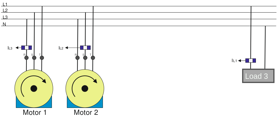
4. Mode 3
If this mode is chosen, L1, L2 and L3 are able to measure a three-phase load. So, the module is able to measure a three-phase balanced load as it was single-phase.
The current, power and energy parameters measured in L1, L2 and L3 will be multiplied by 3 in each parameter, since it is a balanced three-phase load.
Metering standard configuration
Three different metering standards can be chosen for the metering standard EM3/EM3_250 configuration: Circutor, IEC62053-23 and IEEE.
1. Circutor
| Parameters | 1st Quadrant |
2nd Quadrant |
3rd Quadrant |
4th Quadrant |
|---|---|---|---|---|
| Phase Current | + | + | + | + |
| Cosinus | + | - | + | - |
| Exported Active Power | . | - | - | . |
| Exported Aparent Power | . | + | + | . |
| Exported Reactive Inductive Power | . | . | + | . |
| ExportedReactive Capacitive Power | . | . | . | + |
| Imported Active Power | + | . | . | + |
| Imported Aparent Power | + | . | . | + |
| Imported Reactive Inductive Power | + | . | . | . |
| Imported Reactive Capacitive Power | . | + | . | . |
| Imported Active Power Demanded | + | . | . | + |
2. IEC62053-23
| Parameters | 1st Quadrant |
2nd Quadrant |
3rd Quadrant |
4th Quadrant |
|---|---|---|---|---|
| Phase Current | + | - | - | + |
| Cosinus | + | - | - | + |
| Exported Active Power | . | + | + | . |
Note
The rest of the parameters follow the signs defined in Circutor metering standard.
3. IEEE
| Parameters | 1st Quadrant |
2nd Quadrant |
3rd Quadrant |
4th Quadrant |
|---|---|---|---|---|
| Phase Current | + | - | - | + |
| Cosinus | - | + | - | + |
| Exported Active Power | . | + | + | . |
Note
The rest of the parameters follow the signs defined in Circutor metering standard.
Full scale configuration
The voltage input of the equipment can be connected directly to the installation to be measured (as long as the voltage to be measured is not greater than 300VAC). This voltage value is computed using the neutral of the installation as a reference.
Voltage transformers
EM3/EM3_250 now supports voltage transformers (VT) of up to 36kVac. For the EM3/EM3_250 to work correctly with voltage transformers, the primary and secondary voltages of the transformer must be provided.
The current calculation is performed using a current transformer. Current transformers have an output current that must match the module model we have. This current can be 1AAC or 250mAAC (not worth 5AAC).
Current inversion
EM3/EM3_250 now supports current inversion. It toggles the current direction of any phase, to avoid modifying connections already installed.
Warning
It is very important to properly configure the full scale values for current and voltage. If not, the measured parameters will not be correct.
Voltage transformers and current inversion new in eManager image release 22.10.
Functionalities
This module can provide 2 different groups of parameters: energy and power. In the table below are shown the parameters related to each group.
| Power Parameters | Energy Parameters |
|---|---|
| voltage | active_energy |
| current | aparent_energy |
| frequency | inductive_energy |
| cosine | capacitive_energy |
| angle | exported_active_energy |
| active_power | exported_aparent_energy |
| aparent_power | exported_inductive_energy |
| reactive_power | exported_capacitive_energy |
| exported_active_power | imported_active_energy |
| exported_aparent_power | imported_aparent_energy |
| exported_inductive_power | imported_inductive_energy |
| exported_capacitive_power | imported_capacitive_energy |
| imported_active_power | - |
| imported_aparent_power | - |
| imported_inductive_power | - |
| imported_capacitive_power | - |
| maximeter | - |
| current_full_scale | - |
| voltage_full_scale | - |
It allows getting a subgroup of parameters relative to the instant POWER on:
- Phase One (alias "L1").
- Phase Two (alias "L2").
- Phase Three (alias "L3").
- The combination of three phases (alias "L123").
It allows getting a subgroup of parameters relative to the accumulated ENERGY on:
- Phase One (alias "L1").
- Phase Two (alias "L2").
- Phase Three (alias "L3").
- The combination of three phases (alias "L123").
It also allows getting the eight subgroups of parameters above, ALL together.
Note
Energy meters can be set back to 0, with the reset command.
LED's overview
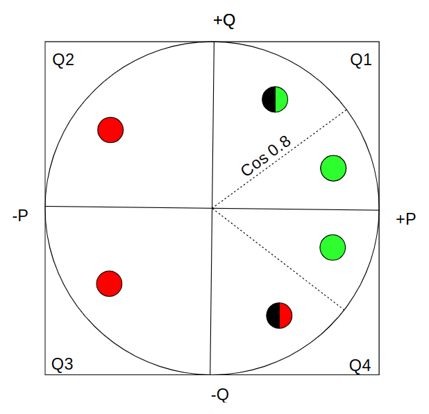
In the image below a representation of the EM3/EM3_250 LED's behaviour is shown. The P axis corresponds to the active power, while the Q axis corresponds to the reactive power.
The LED's have 4 possible states, where different states shown in which Quadrant is the EM3/EM3_250 working and the range of the cosinus:
- Green: cosinus is between 1 and 0.8 (Quadrant 1) or between -1 and -0.8 (Quadrant 4).
- Flashing Green: cosinus is between 0.8 and 0 (Quadrant 1).
- Red: cosinus is between 0 and -1 (Quadrant 2) or between 1 and 0 (Quadrant 3).
- Flashing Red: cosinus is between -0.8 and 0 (Quadrant 4).